


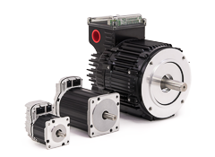


If you need a DC power supply for your stepper or servo motor application[1][1], you have three types to choose from:
- Unregulated, “bulk linear” supplies[2][2]
- Regulated, PWM switching-mode power supplies (SMPS or “PWM switchers”)
- Hybrid, regulated “resonant mode” supplies
Motion control applications have some unique requirements compared to most applications. In brief, motion applications have two requirements that are particularly unique: 1) they have a peak power demand that is typically very high relative to the average demand; and 2) the motors often act as a generator, rather than as a load, and pump current into the power supply rather than drawing from it. (We’ll call this generator effect “regen”, short for regenerated energy.)
Bulk linear supplies basically boil down to three components: a transformer, rectifier, and large filter capacitor. They are fairly well-suited for motion applications, but are big and heavy. Additionally, because they’re unregulated, their output voltage can droop significantly during high peak power demand.
Regulated, switching power supplies are the most widely available of the three types and can have a low cost per watt of average power. On the other hand, you need to put in extra work and cost to ensure they can deal with the high peak power demand and regen associated with motion applications.
Hybrid, “resonant-mode” supplies (aka, RDFC or resonant discontinuous forward-converter supplies), are less common than bulk linear supplies and switchers, but are better suited for the unique demands of motion control applications.
This article discusses the technical considerations that are unique to motion control and compares the three power supply types. If you already have a bulk linear supply or a switcher you were planning to use, you will learn what modifications may be necessary to optimize them for motor power applications.
What Considerations are Important for a Servo or Stepper DC Power Supply?
It’s important to consider the unique demands of a motion control application when selecting a power supply. During accelerations, motor drives can quickly draw large amounts of power. Additionally, motors can create regenerative energy and push current back into the power supply during deceleration (i.e. they act as generators), which means the power supply needs to handle the resulting increase in voltage. Highly dynamic motion applications (ones with large inertial loads, fast accelerations / decelerations and high peak velocities) place large and rapid demands for current on the power supply.
There are many other important factors to consider when choosing the best power supply that are not specifically related to motion control. Some of these considerations are especially important to OEM machine designers looking to minimize the cost of their product and provide reliable operation over a wide variety of operating conditions.
The table below lists the main factors to consider when selecting a power supply. The definitions for each term are summarized here for convenience, but will be discussed in detail later on in this article.
| Peak Power | The maximum output for a short period (typically a few seconds). |
| Average (RMS) Power (aka, continuous power) | The output power that the supply can provide on average (root mean squared average, or RMS) over a long period of time. If the output power demand is constant, this could also be called the continuous power output[3][3] — the power that could be supplied indefinitely. The average power is typically limited by thermal considerations. |
| Load Regulation | The stiffness and stability of the nominal output voltage as the load current changes. |
| Line Regulation | The stiffness and stability of the DC output voltage as the AC line voltage changes. |
| Physical Volume | The x-y-z dimensions making up the power supply volume, including required space for connectors, cables, and ventilation spacing. |
| Weight | The total weight of the power supply (this drives packaging and shipping costs and can also impact mounting locations). |
| Cost: ($/watt-peak) ($/watt-continuous) | The total cost divided by both the peak and continuous output power specifications. |
| Regen Control | The power supply’s ability to handle returned energy from decelerating or gravitational loads. |
| Additional Features | The range of special features for diagnostics, safety, etc. (e.g., LEDs with informative blink codes, rapid discharge of stored energy). |
| In-Rush Current Limiting | The built-in circuitry to limit the instantaneous current draw when AC power is initially applied to the supply. In-rush limiting helps avoid nuisance trips of the AC supply circuit breaker. |
| Protection Features | Features such as short circuit protection, thermal overload protection, reverse polarity protection, etc. |
- Required Power (Peak and Average) — How do your peak and average power requirements differ?
A pumping application which generally runs at a fixed or slowly varying speed and torque, uses a peak power fairly close to its average (continuous) power. A pick & place machine on the other hand, with lots of starts and stops at high acceleration, has a much higher peak than average power demand.
For a well-designed system, you’ll need to consider the peak and average power draw for all axes combined (which, usually, is not simply the sum of the individual axes’ requirements). A multi-axis machine with axes that have overlapping motion profiles (i.e. the axes may accelerate at the same time) will likely require much more peak power than machines where only one axis moves at a time.
The graph below displays the velocity during a typical “trapezoidal” move versus both the peak and average (RMS) power (in Watts).
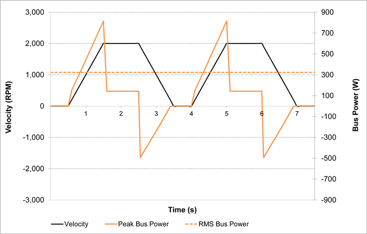
The RMS average power demand for this repeating move is about 323 watts. However, the peak power is over 800 watts or more than 2.5x the RMS power requirement. You can see why it’s important to select a power supply for both the peak as well as the average demand.
- DC Output Voltage Level — What DC voltage is optimal for my application?
This is a trickier question than it appears at first glance. Assuming you want the lowest overall cost for the mechanical power your application needs, and that you are using motors in the 100 watt to 750 watt range (fractional horsepower), there is a sweet spot around 65-85 volts DC.
Many people want to use a 24 volt power supply because these supplies are very easy to find, or because their application already needs 24 volts (for sensors and other components). Many motors, including most of Teknic’s motors, can be run from a 24 volt supply, so why not use 24 volts?
The main reason is that increasing the motor’s supplied bus voltage (to a point) is the lowest cost way of getting more motor power. The mechanical power from the shaft of a motor at any given speed is the speed multiplied by the torque. The maximum speed of any motor is directly related to its supplied voltage. The amount of torque you can get from a motor is proportional to the current you push through its windings, which in turn, is also limited by the power supply voltage. So, the way to get the most power out of any given motor (speed x torque), is to increase its supplied voltage.
Additionally, for any given voltage, a motor will spin faster if the motor’s stator coils have fewer turns of copper wire. And with fewer turns, you can use heavier gauge wire, which will have lower resistance and provide more current per volt. So, why not use a motor with fewer stator coil turns and use a lower power supply voltage?
You can, to a point, but there are tradeoffs. Resistive losses in the drive and the power supply are proportional to the square of the current, so as the current goes up, the drive and power supply have to dissipate a disproportionate amount of heat. Additionally, it’s harder to pack copper wire into a motor stator when you’re using relatively few turns of large diameter wire compared to when you’re using more turns of small diameter wire (as an analogy, think of the amount of wasted space in a jar filled with rocks versus one filled with sand). Less copper fill for any given motor geometry means less motor power.
Conversely, why not use really high voltage? Again, tradeoffs. For motors larger than 1-2 horsepower, it would be impractical not to use high voltage. But for fractional horsepower motors, the use of high voltage brings a number of safety and regulatory issues that increase project complexity and increase cost. When using a supply in the 75 VDC range, the current required to achieve motor power up to 1-2 horsepower is not high enough to worry about the resistive losses and copper fill issues described above. And at 75 VDC, it’s pretty easy and inexpensive to meet electrical safety regulations[4][4].
Below is an example of the torque/speed curves for the same servo motor system powered from three different DC voltages: 24V, 48V, and 75V:
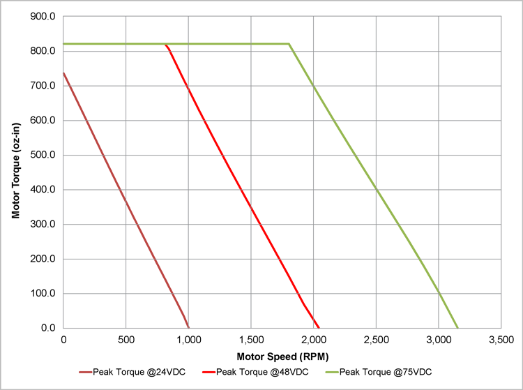
You can see from the torque/speed graphs and from the summary table below, that there is a significant difference in mechanical shaft power that you can get from the same motor just by increasing the supply voltage. Note that, at 24VDC, the motor doesn’t have enough voltage to achieve the peak torque (815 oz-in) that is possible at 48 and 75 VDC.
| 24 VDC | 48 VDC | 75 VDC | |
| Peak Power (W) | 134 | 509 | 1,092 |
| Average Power (W) | 102 | 238 | 391 |
Depending on your exact requirements, you might be able to use a lower than optimal voltage and still get the mechanical power you need. That said, to do so, you’ll probably have to use a larger and more expensive motor than you’d otherwise need.
For example, if your application, after allowing for appropriate design margin, needs 500 oz-in of torque at 2,100 RPM, either motor shown below will work. But the 3436D model running at 48 VDC is longer and more expensive than the 3421P model running at 75 VDC.
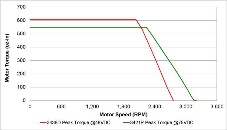
The smaller motor running at 75 VDC has almost the identical peak power as the larger motor running at 48 VDC (it has lower peak torque, but higher speed). The smaller 3421P motor running at 75 VDC has 33% more continuous power (more continuous torque and at a higher speed), and depending on the exact model, it’s almost $90 cheaper, 0.75 inch shorter, and 1.4 pounds lighter.
- Load Regulation/Output Voltage Stiffness — How does the output voltage vary under load?
The voltage output of power supplies will droop (be reduced) to some extent as the supply’s load (the demand for current) increases. The amount of droop depends on the type of supply, the quality of the design, and the amount of load.
As the supply output voltage decreases, the maximum available motor shaft power decreases. Motor drives act as power converters, so some amount of droop can be momentarily compensated for by the drive because it will simply draw more current to provide the required power to the motor drive. But, because the droop reduces the voltage supplied to the motor, the maximum motor power will also be reduced (as described earlier, reduced voltage means reduced maximum speed, and thus reduced maximum power).
When selecting a power supply, you should consider worst case voltage droop across all application parameters (e.g., varying inertial loads, increased friction, higher ambient temperatures, etc.). Power supplies that experience too much voltage droop can cause motor position and velocity errors. With high enough droop, a stepper motor will lose steps and a servo may issue a shutdown due to excessive instantaneous error.
- Line Regulation — How does the output voltage vary as the AC line voltage varies?
There is a wide range of nominal AC voltages across the world. And any given nominal AC voltage can vary by location, time of day, and power grid load. For example, a facility may have a nominal AC line voltage of 115 VAC, but during the middle of a hot day when the power grid is loaded, the actual line voltage may only be 104 VAC. It might be even lower if there is some voltage drop in the facility’s electrical distribution.
Regulated power supplies generally handle any reasonable change in AC line voltage well – they typically have very little output voltage change. But the output of an unregulated supply, like a bulk linear supply, will change proportionately with the change to the input line voltage. So, from the example above, if the AC line dropped 10 percent (from 115 to 104 VAC), the DC output of a bulk linear supply would also drop 10 percent. If your machine needs full output voltage to reach its target motor speed, and was tested at full line voltage, you may be in for a bad surprise when the machine is operated in low line conditions.
A high line AC condition can also be a problem for applications without line regulation. Most motor drives protect themselves from over-voltage conditions, but if the DC bus voltage on an unregulated supply increases due to a high AC line, your drive will now operate closer to its over-voltage limit. This decreases the design margin with respect to regenerative energy because regen will also act to increase the voltage seen by the motor drive.
OEM companies sell and ship their machines to a variety of locations (with different operating voltage conditions). These companies need to consider the different AC sources available at any customer site (in many cases worldwide) and test their machines for the worst-case voltage conditions.
- Regeneration Control Support — How well does the power supply handle a “regen” condition?
All electric motors (DC brush, brushless, induction, stepper or servo) generate a reverse voltage (“back-EMF”) when producing torque against the direction of the motion (e.g., during deceleration). This generator effect (“regen”) pumps current back into the supply and increases the total bus voltage. There are various ways of dealing with this reverse flow of current.
You can add capacitance in parallel with the supply output to act as a reservoir that absorbs this regen energy and stores it for reuse later when power needs to be drawn from the supply. This is similar to how an electric car works. In city travel, regenerative braking restores some of the car’s battery charge and reduces the overall energy consumption and brake wear.
A large output capacitor takes up space, is relatively expensive, and has a relatively low life span compared to other electronic components. The life span issue can be mitigated by choosing a capacitor with a significantly higher voltage rating than the nominal supply voltage. A 90 volt supply will stress an electrolytic capacitor rated for 100 VDC much more than a 75 volt supply.
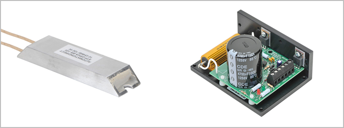
If your axis or machine produces significant regenerated energy (e.g., it rapidly decelerates large inertial loads or has to decelerate loads against the force of gravity), you may have to consider a dedicated regen circuit to shunt current through a load resistor to burn off the excess energy.
Most regulated power supplies are not designed with a regen control circuit or a sufficient output capacitor, simply because most loads in non-motion control applications are passive and do not create regenerative energy. When these regulated supplies are connected to a regenerating load, their output voltage rises quickly and often triggers an over-voltage shutdown almost immediately on the power supply or motor drive.
You can also incorporate a separate output capacitor with associated “blocking diode”, and/or a regen control circuit with its associated load “braking” resistor. The capacitor will function passively to absorb some amount of regenerated energy (and provide it back as needed); the regen control circuit senses when the output voltage exceeds a threshold and shunts the energy through the braking resistor (dissipating the energy as heat). Both methods help keep the bus voltage closer to the nominal level.
These extra components (shown below), along with the requisite wiring, add expense, cabling complexity, and take up more cabinet space. Additionally, the braking resistor can get hot enough to be a safety hazard and may require steps to prevent user injury. The output capacitor may need some additional circuitry in order to prevent in-rush current from tripping your circuit breaker upon power up, as well as circuitry to dump the stored energy upon power down.
- Size/footprint — How much room is required for the power supply, cables, and any other ancillary components?
Size and/or form factor are important for most machine builders and the motion control power supply is often one of the largest components found within an electrical cabinet. Electronic cabinets or enclosures (especially if rated for a harsh environment) are expensive. Smaller supplies and fewer components (e.g., output capacitors, braking resistors, etc.) decrease space requirements and costs.
- In-Rush Current Protection — How does the power supply handle the initial power-on surge of current?
In-rush current is the initial, instantaneous current that a component draws when it is first powered on. Uncharged capacitors will draw lots of current as they begin charging. In-rush current for a DC power supply can be many times greater than steady-state input current. Without in-rush current limiting circuitry, power supplies can trip correctly-sized circuit breakers or blow fuses when powered on. Later, we’ll describe how a NTC thermistor (negative temperature coefficient) can be used to help with in-rush.
- Other Helpful Power Supply Features
- Diagnostics: Some supplies offer different color LEDs or other indicators that can help engineers and technicians troubleshoot power issues.
- Safe discharge: Output capacitors large enough to handle regen store a lot of energy. If this energy is not safely dissipated after power down, it can take a long time to self-discharge. This stored energy can be hazardous or even allow some motor rotation. Safe discharge circuitry quickly discharges stored energy within the power supply when AC input power is removed.
- Short-circuit protection: At some point, especially for OEMs who are building the same machine over and over, someone will accidentally mis-wire the supply, shorting it to ground. This can also occur if the motor drive fails, or if the wrong cable gets pinched. Short-circuit overload protection will save time and money while minimizing collateral damage.
- Cost — What is the fully burdened price of the power supply, including installation cost, and any additional circuitry and required third-party components?
OEM machine builders can be particularly sensitive to costs because they become significant as machine volume increases. It is important to consider the cost and labor associated with integrating ancillary electrical components (such as an external regen control circuit, blocking diode, braking resistor, or additional capacitors).
Other costs that are often forgotten are the shipping and handling costs. Some power supplies are large and heavy, and the shipping costs[5][5] can add up quickly.
How do the Three Power Supply Choices Compare?
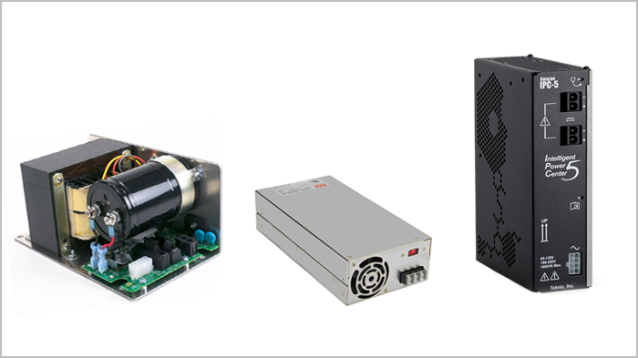
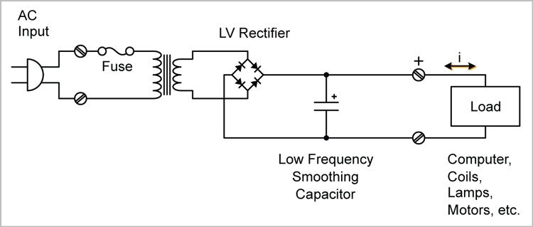
Unregulated, Linear Power Supplies
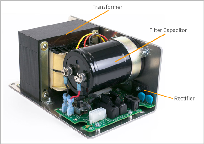
One of the simplest power supplies around, the bulk-linear, unregulated power supply has 3 main components.
- Transformer: The primary transformer converts the input AC line voltage to an alternative AC voltage (typically the final, desired DC voltage level). E.g. 115 VAC to 75 VAC.
These laminated-core transformers take up a lot of space and their steel laminations and copper windings are heavy. Toroidal transformers can be substituted, as they are somewhat smaller and more efficient (they have a lower parasitic or internal resistance), but they are more expensive due to a more complicated construction technique and they are still relatively bulky and heavy.
- Full-Wave Bridge Rectifier: The bridge rectifier is an array of diodes (typically in one package) that converts the negative half cycle of the transformer’s AC output voltage into a positive voltage. The output of the rectifier has twice the frequency of the input AC, but only positive polarity.
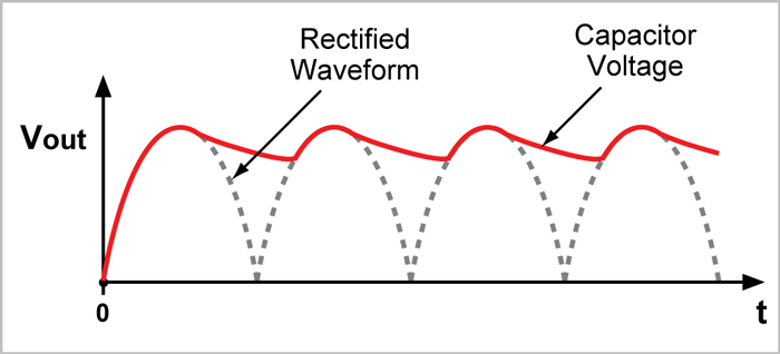
- Capacitor: The output capacitance filters the AC half-sine pulses from the rectifier and provides a DC output with some amount of AC ripple riding on it. The capacitance stores energy so that even if you pull current from the supply during the phase of the AC input where the voltage is low, the output voltage won’t droop too much. Of course, the more capacitance you have, the more energy storage, and the less droop for any amount of load. A larger capacitance will also absorb more regenerative energy generated during deceleration periods.
Below is a schematic for a bulk linear power supply:
Bulk-linear power supplies have a number of advantages:
- They are simple and therefore, relatively easy to manufacture. The most basic versions have only three primary parts (a transformer, a rectifier, and an output capacitor) so their MTBF (Mean Time Between Failures) numbers will be correspondingly high.
- The simplicity of these supplies also helps keep their cost lower (although prices can vary as steel and copper prices fluctuate).
- The minimal number of components (typically all passive circuitry) also makes these supplies electrically quiet (they aren’t sources of emissions and are largely impervious to outside electrical noise). These unregulated supplies will pass on only their source AC frequency of 120Hz (after full wave rectification). This low frequency is insignificant for most applications.
- The generally large transformer and output capacitor provide an ample, readily available source of current, well suited for high peak loads. The capacitor also acts as a reservoir to absorb the energy generated by a motor decelerating an inertial load.
- The transformer also has a substantial thermal inertia so it is capable of delivering a higher output peak power (typically 2-3X the average power) for an extended period before overheating.
There are several disadvantages of unregulated, linear power supplies:
- They have more voltage ripple than most designs because the AC input voltage is well below the DC output voltage for a relatively long time. A large output capacitance will help smooth this voltage ripple.

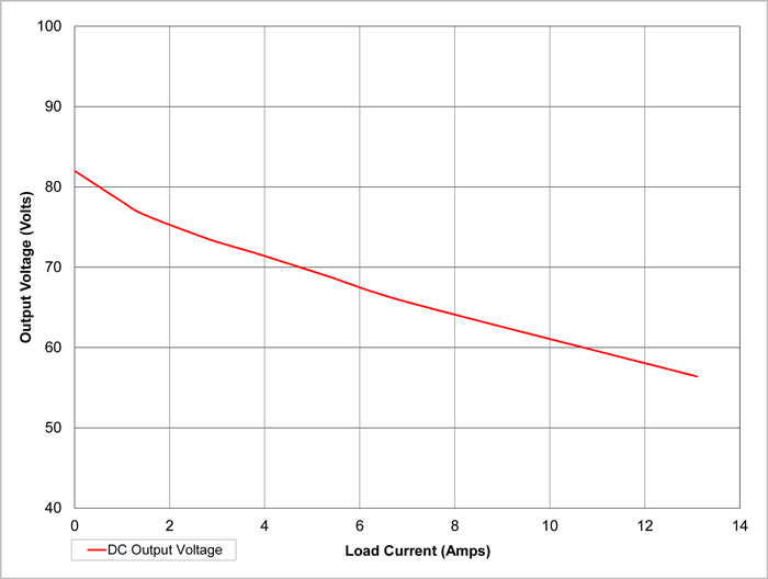
- Even with a substantial output capacitor, the output voltage of an unregulated supply will droop when loaded. As shown below, the amount of droop for any given power supply is primarily a function of the load. The droop would be more or less with a smaller or larger output capacitor, respectively.Figure 8: Output DC Voltage versus Current Load (Model E3PS12)
If the voltage droops too far, the stepper or servo motor will not have enough voltage to spin at the required speed. This will lead to higher position and velocity errors in any system and will cause stepper motors to stall. This voltage droop can be significant and engineers should test that their application works properly when the supply is loaded to the expected maximum.
- Note that droop is not necessarily bad in a motion control application. This is because maximum voltage from the supply is only needed at high speed where the generator effect of the motor (the back-EMF) is canceling out much of the power supply voltage. If your motion application needs a lot of current (for a lot of torque), but not at high speed, the droop may not affect you at all.
So with a bulk-linear supply, you can get your power from low current and a voltage close to the nominal (i.e., without much droop). Or, you can pull a lot of current (causing droop), but if your motor speed doesn’t require full voltage, you’ll still get a lot of power. As we’ll discuss later, this is not something that a PWM switching supply can do. These supplies produce DC voltage output that varies in direct proportion to the input AC line voltage. Not only does the line voltage vary by region in the world (for example, Japan’s standard is 100 VAC), it can vary by time of day or even location within a factory[7][7]. Line frequency will also affect the DC output because each cycle of a 50 Hz AC input takes longer to charge the output capacitor than a 60 Hz AC input.
You can add “taps” on the transformer for high line and low line conditions to help maintain the desired DC output voltage across different AC line voltages, but this adds cost to the transformer and can be time-consuming to adjust (for example, some transformer taps require a hand soldering operation). Additionally, the taps won’t account for AC voltage variations over time or if the location is changed because you usually only set the transformer tap one time (usually when the machine is installed)
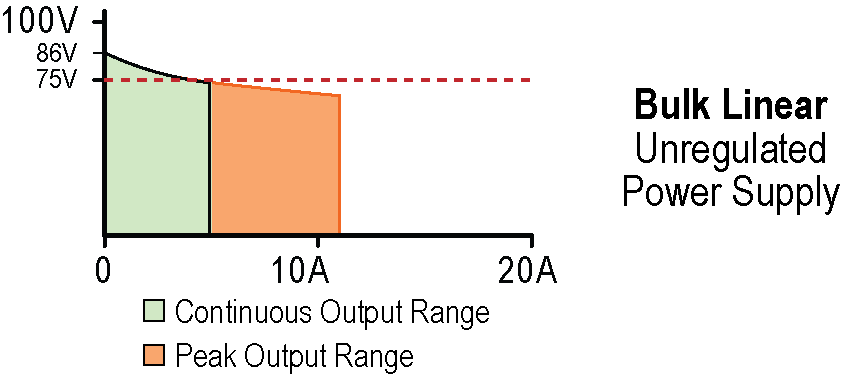
- An unregulated, bulk-linear power supply generally has an unloaded output voltage well above its specified nominal level. This is so that the output voltage is closer to the specified nominal voltage after the supply droops from an average load. But when the load is light or the motor is regenerating, the voltage will rise and can cause issues such as over-voltage faults or possible damage to upstream devices.
- Bulk-linear power supplies are relatively big and heavy, which makes it harder to fit them into a compact machine. Their size and weight also increases packaging and shipping costs. For example, shipping a 12 pound supply versus a 2.2 pound supply via UPS Ground from New York, USA to California, USA costs almost $10 more (about a 5-10 percent cost increase). If any type of expedited shipping is required, the costs increase dramatically. If you ship those two supplies via UPS 2-day, the costs differ by almost $60.[8][8].
- Not all bulk-linear power supplies are well-suited to handle regen. The returned energy from a motor will charge up the output capacitor, increasing the DC output voltage. If the capacitor is sized mainly to minimize ripple without considering regenerated energy storage, the DC output may increase to the point of causing an “over-voltage” shutdown on the motor drive. This can also happen if the no-load voltage is close to the over-voltage limit of the motor drive because there will be little allowance for any regen.
- Unless the bulk-linear, unregulated power supply has in-rush current limiting (relatively rare), a high amount of current will be pulled from the AC line upon power up (as the output capacitor charges). This can trip circuit breakers or blow fuses. You can solve this problem by wiring a negative temperature coefficient resistor in series with the AC input line. Upon initial power-up, when the resistor is cool, the resistance is high which limits the current. As the resistor heats due to current flow, the resistance drops to a low value. However, you do lose some efficiency and the increased wiring and components add cost.
- Bulk-linear, unregulated power supplies are typically “bare bones” devices, and don’t have a variety of useful features found in other supplies such as diagnostic LEDs or discharge of stored energy upon power down. Also, most bulk-linear supplies are not enclosed, so you will need to fabricate an enclosure of some sort if user shock protection or mechanical protection of the circuitry is important in your application. Similarly, some of the electrical features can be added (like in-rush limiting, or an external regen control and load), but doing so increases costs and wiring complexity while decreasing reliability and available space.
In summary, bulk linear power supplies have a few disadvantages that you should consider before using them in a motion control application. These supplies will experience notable droop under load, lack additional features helpful for safety or troubleshooting, and they can easily cause over-voltage shut downs or other issues on your motor drive. If your application doesn’t experience regen and it can tolerate droop during the acceleration phase, this style power supply may be perfectly adequate.
In spite of the disadvantages, unregulated, bulk-linear power supplies are common in motion control applications because of their simplicity and low cost. Next we’ll review another popular power supply type: the regulated, switch-mode supply.
Regulated, Switched Mode Power Supplies
A regulated, switching power supply includes control electronics designed to maintain the output voltage at the specified level regardless of load. Switchers (also referred to as a Switched-Mode Power Supply (SMPS)) incorporate active circuitry and are more complicated than their bulk-linear, unregulated counterparts. Switchers actively regulate their DC output voltage using a technique called “pulse width modulation” (PWM) and feedback. There are a range of different electrical components within a switching, regulated power supply. Below is a typical schematic.
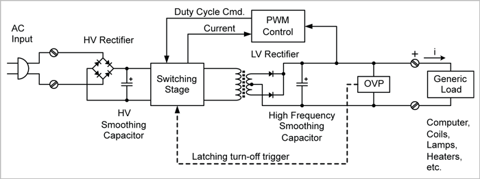
The block diagram of a typical switch-mode power supply has five blocks:
- Input Rectifier and Filter: Consists of a rectifier (diodes wired to invert the negative cycle of an AC waveform) and a filter capacitor to convert the rectified AC voltage to a DC voltage.
- Inverter Chopper: Consists of a multistage power transistor circuit to convert the DC voltage to a higher frequency AC voltage (usually well above 20 kHz, so as to be inaudible). This AC voltage is pulse-width-modulated to create a variable duty-cycle AC voltage.
- Transformer: Converts the AC voltage produced in the previous step to the desired amplitude. These transformers run at relatively high frequencies and can thus be smaller in size than transformers designed to run at line frequencies (their ferrite cores have low losses at high frequencies).
- Final output rectifier stage and filter capacitor: Consists of more diodes (rectifier) and a filter capacitor to convert the PWM AC voltage to DC.
- Voltage regulator: Consists of a semiconductor device as part of the feedback circuit to monitor the output voltage with respect to a reference voltage. The duty cycle of the PWM is varied to maintain the desired output voltage.
The advantages of switching power supplies are summarized below:
- Switched mode power supplies produce a nearly constant voltage regardless of load because they have active circuitry to regulate the output voltage. As long as you use them within their specified current range, you won’t see much voltage droop under load. This can provide a notable performance advantage over unregulated supplies.
- Switchers have a smaller volume and are lighter than unregulated power supplies. Their transformers are significantly smaller and the output capacitance is much lower.
- Most switching power supplies directly accept a wide range of AC input voltages, usually 100-240VAC, with line frequencies of 50 – 60 Hz. Wiring the AC input is generally easy, as there is no bulky input transformer with high/low line taps – all voltage regulation is electronically controlled.
- The circuitry within switching power supplies usually comes standard with “soft start” or in-rush current limiting. A properly specified switcher will generally not trip circuit breakers when power is turned on.
- Most switchers also have some form of overload protection. Many of these supplies will automatically shut down if the load is too demanding and will not supply dc output power until you first cycle AC input power.
On the other hand, there are several notable disadvantages of switching power supplies:
- Switchers generally have little peak capacity. The peak power output is typically only 15 to 20 percent more than the continuous rated power. In addition, this peak capacity is only available for brief bursts of time. Motion applications require peak power for the duration of the acceleration of the load; this typically takes much longer than the amount of time that a switching power supply can provide peak power. This means that you have to purchase a switcher with a high enough continuous power rating to meet the peak power demands of your application.
Let’s refer back to the standard trapezoidal motion profile as shown earlier in Figure 1. As we highlighted, the average power load of this profile (with a 0.5 sec pause between moves) is about 320W, but the peak power demand is 815W or almost 2.6x the average requirement. So, in order for a switch mode supply to operate properly (without shutting down), you’d need to select a power supply with at least 850W continuous capacity –a larger and more expensive supply.
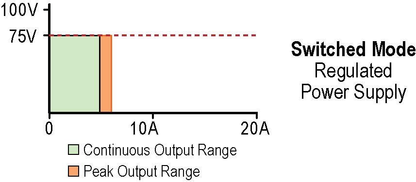
The graph below shows the voltage output for a typical 350W switching power supply. The graph also shows that most switchers actually have, for brief periods of time, some peak power output capability (roughly 20% more than their continuous rating). This supply has enough continuous power to handle the above application, but would shutdown during the acceleration phase. If your application tries to push, even briefly, the supply much past its continuous limit, it will almost immediately experience some type of safety shutdown or cutback mode.
Figure 12: Voltage versus Load for a 350W Switching Power SupplyAs compared to the output regulation of a switcher, the voltage droop of an unregulated bulk-linear supply is normally considered a disadvantage. However, it does enable you to pull substantially more power for brief periods of time (well-suited for acceleration portions of a move profile). This can be an advantage relative to a switching supply which holds the output voltage constant and cannot give you more current.
- Although there is a wide range of choices at lower voltages, the availability of switchers with an output above 48VDC is somewhat limited. Many DC input servo and stepper drives can utilize 60 to 90VDC, so if you choose a lower output voltage power supply, you forgo a substantial amount of mechanical shaft power.
- All electric motors will generate regenerative energy (i.e. the motor acts as a generator) when they deliver torque of an opposite sign to the direction of motion (for example, negative torque for a positive move). The motor returns this energy to the power supply’s DC voltage output, increasing the voltage. Switching power supplies do not have sufficient output capacitance or a separate regen circuit to absorb and/or dissipate this energy. As a result, the power supply and/or the drive will trigger an over-voltage shutdown.
Additionally, switching power supply designers typically set the “over-voltage” protection threshold low because they do not expect the reverse flow of energy (such as regen). This just exacerbates the tendency for these supplies to shut down with only a small amount of regen.
Adding an external output capacitor with a blocking diode in front of a switcher will help with regen, but this requires more space, adds wiring, increases manufacturing labor, and raises costs.
In summary, although PWM switching supplies have a number of drawbacks for use in motion applications, they can be successful, particularly in applications that have more continuous loading (e.g., pumps and mixers) as opposed to applications with more peak demands (e.g., multi-axis machines with frequent motor accelerations and decelerations).
In applications with peak power demands well in excess of the continuous power demands, you may find that you need to use a relatively large switching supply and add external circuitry to handle regenerated energy.
Hybrid Power Supplies Designed for Stepper or Servo Motor Control
Despite the disadvantages of bulk-linear supplies, Teknic has historically recommended them (over switchers) for motion control applications because switchers need to be significantly oversized to handle the typical peak loads. Switchers also almost always require some additional user-supplied circuitry to work reliably (e.g. extra output capacitance and blocking diode and/or regen controller and load).
Bulk-linear supplies can supply the high peak power usually required for motion applications (albeit, with output voltage droop) and they have a moderate amount of regen capacity due to their typically large output capacitance.
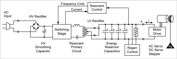
A few years ago though, we realized that an RDFC[9][9] supply (a switching supply that uses a resonant discontinuous forward-converter instead of a PWM switching stage) could be designed to handle large peak loads.
In an RDFC or “resonant mode switcher”, the switching transistors only turn on and off when they are in a “no-current” or “no-voltage” state. In the more common PWM switcher, the transistors will switch at full power, and their silicon die have to dissipate a lot of heat. Because of this, any amount of power usage in excess of the continuous rated power will quickly heat up the transistors to a damaging level.
In the resonant mode switcher, the transistors dissipate much less power, so the thermal limit in this type of supply is the transformer’s thermal limit. The transformer has much more thermal mass than the silicon inside the transistors, and thus can absorb much higher peak loads and longer duration peaks[10].[10].
If you combine a resonant mode switcher with a healthy amount of output capacitance and a regen controller, you have a hybrid power supply that is ideal for motion control applications. This hybrid design combines all of the advantages of the PWM switching supply (primarily its voltage regulation with respect to line and load variation, and its small size and low weight), with the advantages of the bulk-linear supply (primarily its peak capacity, regen capability and low EMI).
The simplified circuit schematic of this hybrid design is shown below.
As shown in the graph below, this design also allows your application to draw significantly more than even the rated peak current without causing a shutdown. Exceeding the peak current rating will cause some droop (while keeping the overall power relatively constant), but as we explained earlier in the bulk-linear section, voltage droop can be acceptable if it allows you to get more current for those moments of high torque demand at lower speed.
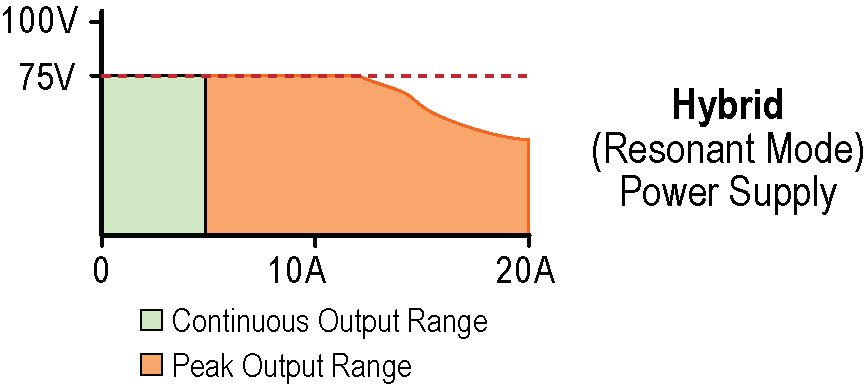
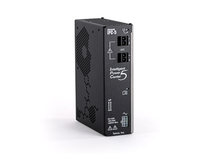
Teknic’s IPC-5 power supply is a hybrid, resonant mode, regulated power supply. It’s rated for 350 watts of continuous power and 900 watts of peak power (a 2.5x peak-to-continuous rating). Its size and weight is comparable to that of PWM switched mode power supplies.
The features of this hybrid supply are designed specifically for motion control applications:
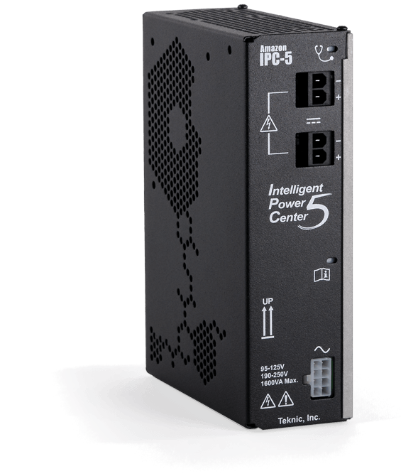
- Optimal 75 VDC output
- Regulated output to provide minimal voltage fluctuation over a wide range of load and AC line conditions
- High output capacitance (9,400 uF) provides lossless storage of regenerated energy, and enhance the peak power rating
- Compatibility with common AC line standards (95-125 VAC and 190–250 VAC, 50-60Hz)
- Built-in regen control (including load resistors)
- In-rush current limiting
- Safety protection features including: output short circuit, thermal overload, over-voltage, and over-current protection
- Automatic fast discharge of stored energy when main AC power is removed
- Compact size and high power density to enable optional DIN-rail mounting; only 2.2 pounds in weight
- Diagnostic LEDs to communicate a range of status information including regen event detected, regen control circuit engaged, regen capacity exceeded, transient over voltage, and safety shutdown conditions
Summary
Motion control applications are unique compared to most DC power supply applications. The most significant requirements for a DC power supply powering a motion control application include a high ratio of peak-to-continuous power supply and the ability to handle regenerative energy (power pumped back into the supply).
The unregulated, bulk-linear supply inherently handles both of these unique requirements, especially if it has high output capacitance. Adding regen control further enhances its ability to handle regenerated energy. Bulk-linear supplies are readily available in the 60-90 VDC range which is optimal for getting the most power out of fractional horsepower motors.
The PWM switching supply has the advantage of maintaining a relatively constant output voltage over a wide variety of AC line input values and load conditions. This makes the PWM switcher more likely to function well in many conditions and over time, especially for OEMs who sell machines into different environments and geographical areas. These supplies are also small and lightweight relative to bulk-linear supplies.
Both types of supplies suffer from disadvantages when used in motion control applications. The main disadvantages of the bulk-linear supply are voltage droop under load, sensitivity to varying AC line conditions, size, weight, lack of protective enclosure, and high in-rush current. The PWM switcher has very little peak capacity, which means you typically have to oversize the supply to avoid overloading it, and it has very little capacity to absorb regen before shutting down.
The resonant mode switching supply, outfitted with high output capacitance and a regen control, provides the best of all worlds when it comes to powering fractional horsepower stepper or servo motors. It has a high peak-to-continuous power rating (high peak power and for a sufficiently long duration), it maintains a relatively constant output voltage over a wide variety of AC line and load conditions, it has the ability to supply very high current (at lower voltage) without shutting down, it can handle a significant amount of regenerated energy, and it has a size and weight similar to that of a PWM switcher that has the same continuous power rating.
Below, we show the voltage output versus load for all three types of power supplies (bulk-linear, PWM switching, and hybrid) to better highlight their differences. To make the comparison fair, we selected supplies that all have average (continuous) power ratings of ~350Watts. You can see, however, that the DC output voltage stiffness (or droop) and peak output capabilities are notably different, but clearly optimal in the hybrid-resonant architecture.
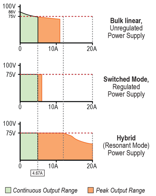
Here is a qualitative summary of the relative differences between the three types of power supplies in the context of a motion control application:
Relative Performance 1 5 PoorExcellent |  Bulk-Linear Unregulated | 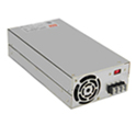 Switching (Unregulated) |  Hybrid (Regulated) |
| Affordability (peak watts/$) | 3 | 2 | 4 |
| Affordability (contin. watts/$) | 4 | 3 | 3 |
| Peak Power | 3 | 2 | 5 |
| Continuous Power | 2 | 2 | 2 |
| Output Voltage Stiffness | 1 | 3 | 4 |
| Physical Size (Volume and Weight)* | 1 | 4 | 3 |
| Regen Control | 2 | 1 | 5 |
| In-Rush Current Protection | 1 | 4 | 4 |
| Additional Features | 1 | 3 | 4 |
*A higher number in the table means smaller average size and weight.
To provide more quantitative information about the three types of supplies, we picked two manufacturers’ part numbers for each type, and reproduced the specifications and pricing below:
| Bulk-Linear, Unregulated | Switched Mode, Regulated | Hybrid | ||||
| Automation Direct: STP-PWR-7005 | Teknic: SSt-3PS12-75 | Automation Direct: PSB48-240S | Applied Motion: PS480D72 | Teknic: IPC-3 | Teknic: IPC-5 | |
| Cost (1-piece) | $200 | $210 | $132 | $385 | $199 | $248 |
| Peak Power | 560 W | 900 W | 240 W | 482 W | 900 W | 900 W |
| Continuous Power | 350 W | 263 W | 240 W | 482 W | 225 W | 353 W |
| Volume | 234 in^3 | 157 in^3 | 78 in^3 | 56 in^3 | 84 in^3 | 85 in^3 |
| Powerpeak Density | 2.4 W/in^3 | 5.7 W/in^3 | 3.1 W/in^3 | 8.6 W/in^3 | 10.7 W/in^3 | 10.6 W/in^3 |
| DC Output Voltage | 70 Vdc | 72 Vdc | 48 Vdc | 72 Vdc | 75 Vdc | 75 Vdc |
| Weight | 16.00 lbs | 12 lbs | 2.12 lbs | 2.40 lbs | 2.11 lbs | 2.25 lbs |
| Watts peak/$ | 2.80 w/$ | 4.29 w/$ | 1.82 w/$ | 1.25 w/$ | 4.52 w/$ | 3.63 w/$ |
| Watts continuous/$ | 1.75 w/$ | 1.25 w/$ | 1.82 w/$ | 1.25 w/$ | 1.13 w/$ | 1.42 w/$ |
| The rows below reference these power supplies’ regen capability. | ||||||
| Native Regen Handling Capability | 5.3 joules | 20.9 joules | < 0.3 joules (virtually none) | < 0.3 joules (virtually none) | 21.6 joules | 28.3 joules |
| Cost to add at least 20 joules of Regen capability | $55 | n/a | $32 | $90 | n/a | n/a |
| $/watt peak (with cost of regen) | $0.46 | $0.23 | $0.68 | $0.98 | $0.22 | $0.28 |
| $/watt continuous (with cost of regen) | $0.73 | $0.80 | $0.68 | $0.98 | $0.88 | $0.70 |
Hopefully, you now have a good understanding of the different types of power supplies along with their pros/cons for motion control applications. Unregulated bulk-linear and regulated switched mode supplies are both common, but have some drawbacks for motion control applications. The hybrid, resonant mode architecture combines the best features of the other supplies and is ideally suited to providing DC power for servo and stepper motor drives.
Footnotes
Questions/Comments?